


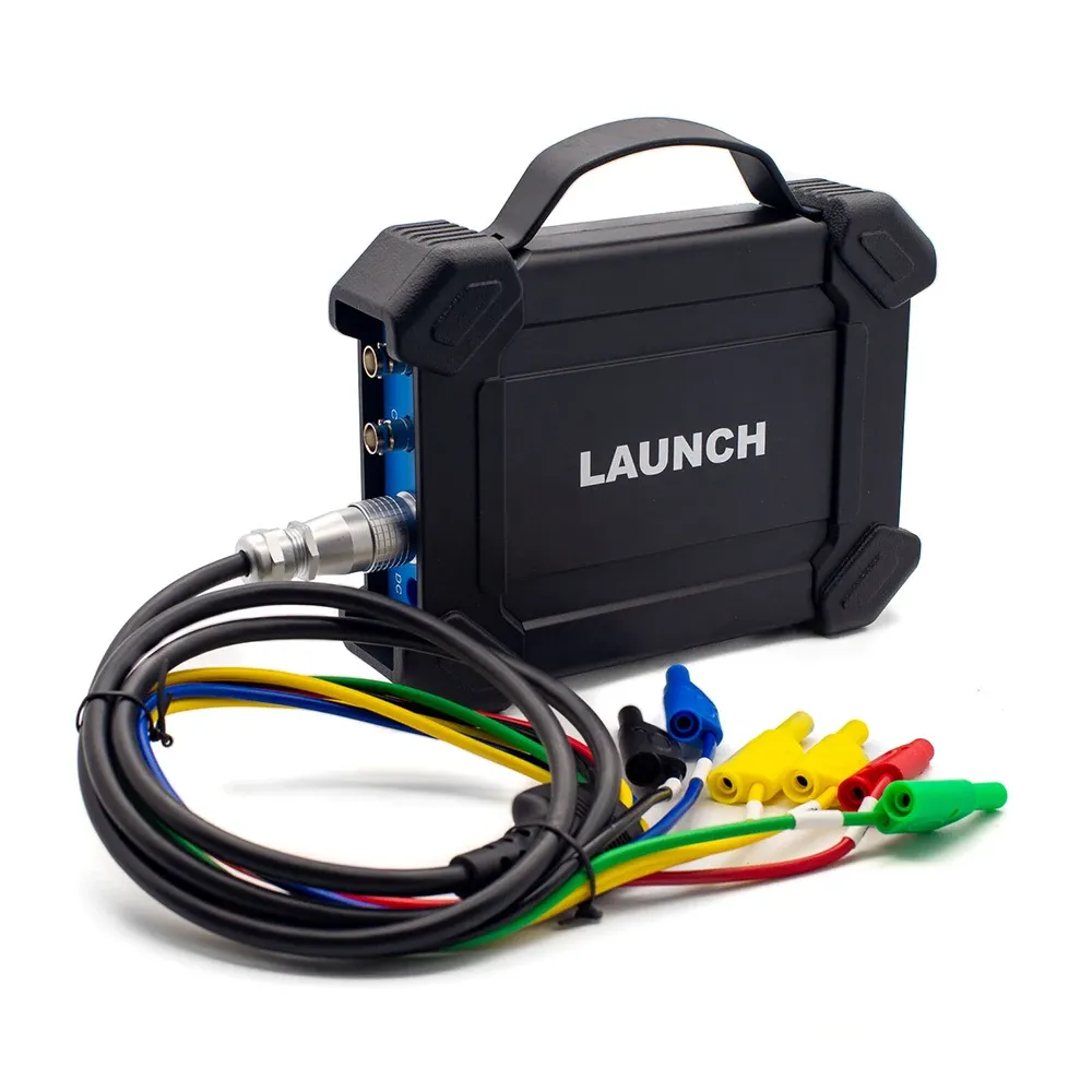

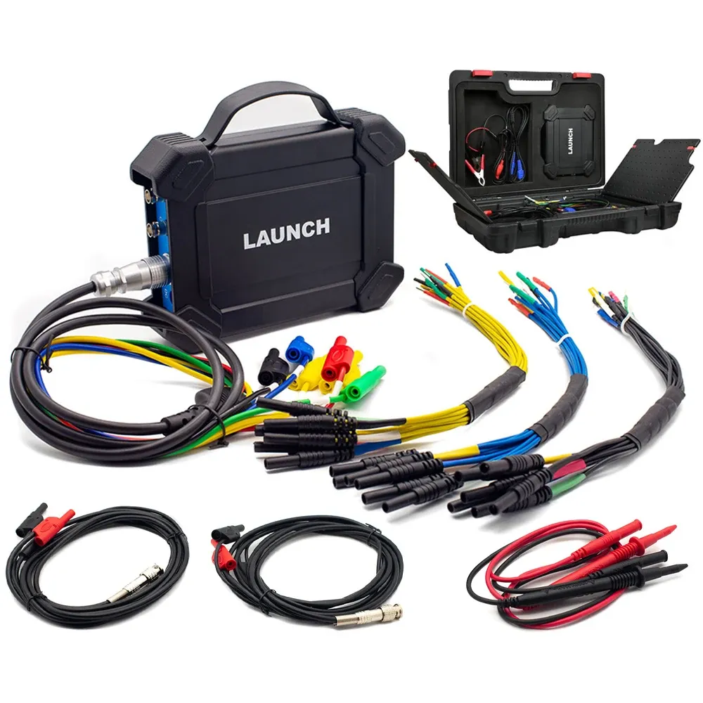
Launch X431 S2-2 Sensor box Tester 2 Channel Oscilloscope Simulator Compatible with X-431 PAD VII X431 PAD V X-431 PAD III V2.0
LAUNCH S2-2 Sensorbox is designed to test and simulate most vehicle sensors, quickly troubleshooting the ECU. It can be compatible with LAUNCH scanner X-431 PAD V and X-431 PAD III V2.0, to maximize the repair shop’s revenue.
Features:
1. Check the ECU itself works or not
2. It supports manual write the waveform data
3. Simulate working condition of sensors without replacing parts
4. Simulate some special working condition of sensors without replacing parts
5. Be used as Multimeter to measures resistance, voltage AC/DC, capacitance, frequency and pulse signals, etc.
6. One click to enters the intuitive menu of sensor, actuator, defined/drawn the waveform, timing waveform, multimeter, system settings.
S2-2 Sensorbox is specially developed for diagnosing/simulating sensor faults. It mainly includes “Sensor”, ” Actuator”, “Defined/Drawn”, “Timing Waveform” and ” multimeter”
*Sensor: Is used to simulate the input signals of the automobile electronic control system, and the automobile computer adjusts the running state of the engine according to these parameters.
*Actuator: Is used to simulate the output control signal of automobile electronic control system, so as to judge the working conditions of automobile actuators such as idle motor, EGR solenoid valve, etc.
*Multimeter: Through this function, users can test voltage, resistance, and capacitance.
The module cannot be used separately, it only works as accessory for LAUNCH X-431 EURO TAB2 diagnostic tools.
Technical Parameters:
Sensor module:
Parameter: Range
Number of channels: 2
Precision: 1 %
Amplitude range: 0 – 20 V
Max output current: 20 mA
Predefined frequency range: 0 – 20 kHz
Square wave signal pulse frequency: 0 – 15 kHz
Square wave signal duty cycle: 0 – 100 %
Power supply: Simulator sensor output/max current 20mA (output is powered by battery) – Drive solenoid, ignition coil/output current 2A (external power supply)
USB: USB2.0 Type B (with charging and power supply function/5V)
DC voltage simulation: Support
Fixed frequency simulation: Support
Predefined waveform simulation: Support
Hand-drawn waveform simulation: Support
Signal generator interface: 2
External power supply port: 1
Solenoid interface: 1
Multimeter interface: 2
Working temperature: 0 °C – 50 °C
Storage temperature: -30 °C – 70 °C
Multimeter:
Parameter: Range
DC voltage: 0 V – 700 V
AC voltage: 0 V – 700 V
Resistance: 0 Ω – 40 MΩ
Capacitance: 0 F – 100 µF (maximum 30 s measurement time)
Diode: 0 V – 1,5 V
Continuity detection: Sounds below 30 Ω
Defined
*Waveform: There are 9 waveforms to choose; Forward sine wave, reverse sine wave, forward square wave, reverse square wave, medium voltage, straight line, high / low voltage straight line, triangle wave, and trapezoidal wave.
*Frequency: Set the frequency of the selected waveform.
*Amplitude: Set the amplitude of the selected waveform.
*Offset: Set the offset of the selected waveform.
*Phase: Set the phase of the selected waveform.
*Duty cycle: Set the duty cycle of the selected waveform.
*Signal sync: Can cause CH1 and CH2 to output signals at the same time.
Hand-drawn
*Total frame: 1-3 (optional). Indicate the total number of output points
*Generally, one waveform is composed of 100 points. The values 1-3 indicate that you can select 100, 200, or 300 points to form a waveform.
*Edit frame: You can edit a single frame or edit all
*Waveform: You can select a preset waveform and place it in the hand-drawing area
*Frequency: Frequency of a single frame (for 3-frame output, the total frequency is the set frequency/3)
*Amplitude: Amplitude of the output waveform
*Offset: Offset of the output waveform

1. COM-Multimeter common
2. V/Ω/C-Multimeter measuring terminal
3. Power button-Press this button to start up and shut down.
4. B-type USB interface-It is connected to the diagnostic device via a USB cable.
5. Battery status indicator lamp (green)-If the green lamp is steady on, the battery electric quantity is normal. If the green lamp is flashing at an
intermediate speed, the electric quantity is low (regardless of whether the red lamp flashes). If the green lamp is flashing at a low speed, charging is in progress.
6. Connection status indicator lamp (red)
a.If the red lamp is steady on, the diagnostic tool is connected. If the red lamp is flashing, the diagnostic tool is disconnected.
b. It will enter the charging status only when the red lamp is flashing. The green lamp is flashing at a low speed during charging (if the electric quantity is full, it will stay on).
7. CH2-Channel 2
8. CH1-Channel 1
9. 7-pin interface-Used to connect 7-pin interface (to six 4mm safety banana head lines) to measure the actuator. When measuring the actuator, it is necessaryto connect the module to the car battery to supply power.
Connection
1) Insert one end (B-type terminal) of the USB cable into the B-type USB port of the sensor module host, and then insert the other end into the USB port of the diagnostic tool.

2) Press and hold the power button for over 3s to start the sensor module. If the electric quantity is normal, the green lamp is steady on.Indicator lamp status description:
Green lamp:
*Steady on: normal electric quantity
*Flashing at an intermediate speed: low electric quantity (regardless of whether red lamp flashes)
*Flashing at a low speed: charging in progress
Red lamp:
*Steady on: diagnostic tool connected
*Flashing: diagnostic tool disconnected. It will enter the charging status only when the red lamp is flashing. The green lamp is flashing at a low speed during charging.
3) Start the diagnostic tool and access the toolbox. Tap Sensor Simulator to access the job menu of sensor.
Job Menu
The sensor module is mainly divided into five functional modules

1) Sensor: Use output voltage or waveform to simulate the working status of the on-board sensor, so as to accurately judge the quality of the sensor and reduce blind replacement of accessories.
2) Actuator: Used to output PWM signal to drive the on-board coil actuator.
3) Defined/Drawn:Users can customize sensor waveforms to facilitate future sensor signal simulation.
4) Timing waveform: Customize timing waveform to match the engine (crankshaft + camshaft), and output in the same phase.
5) Multimeter: universal multimeter functions.
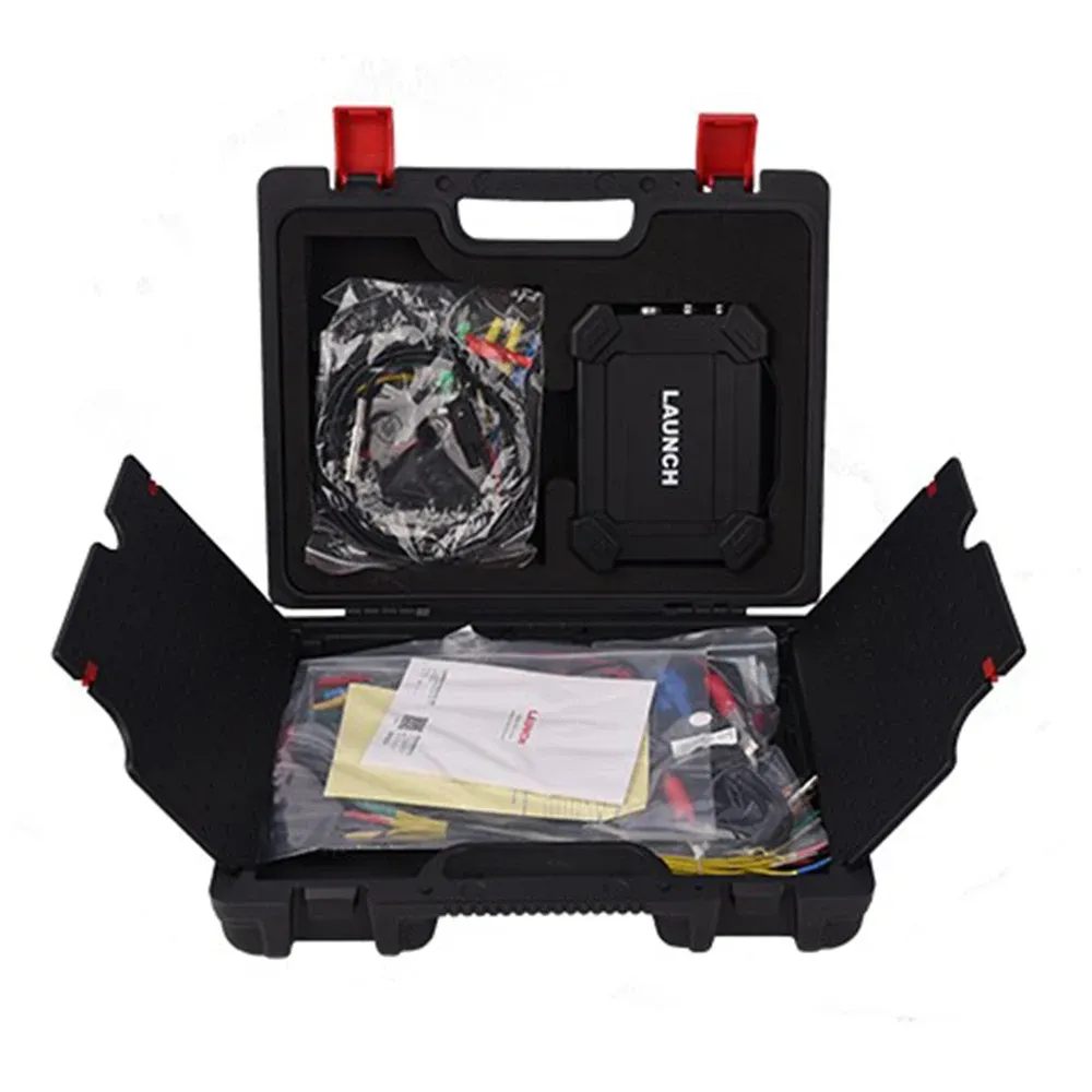
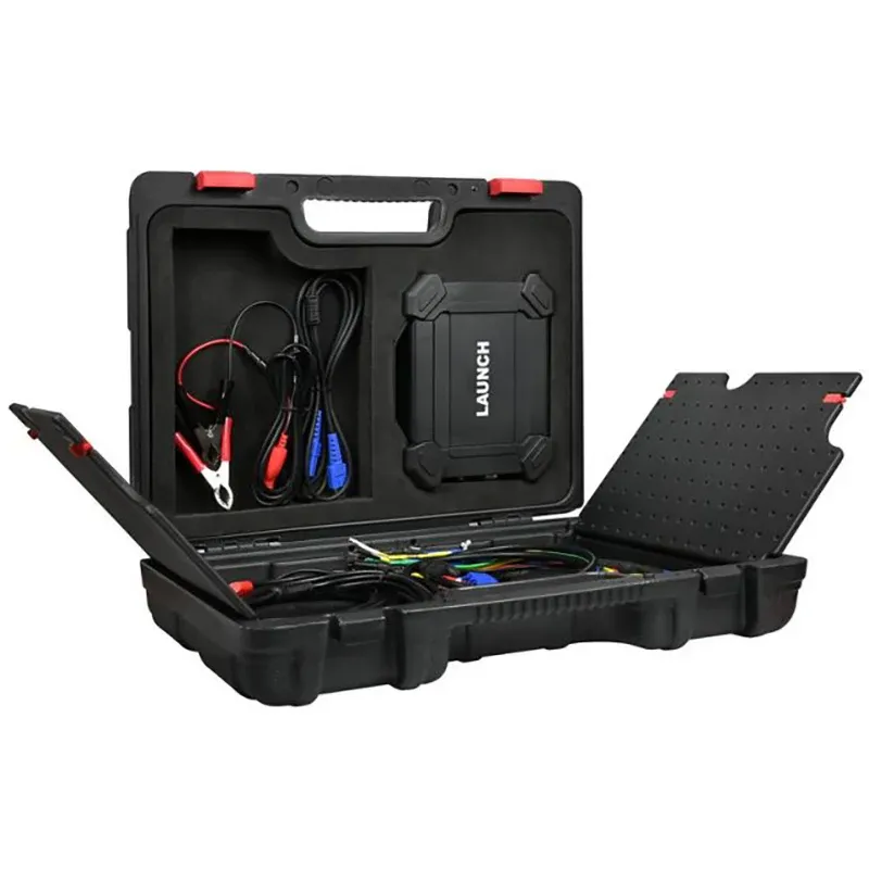
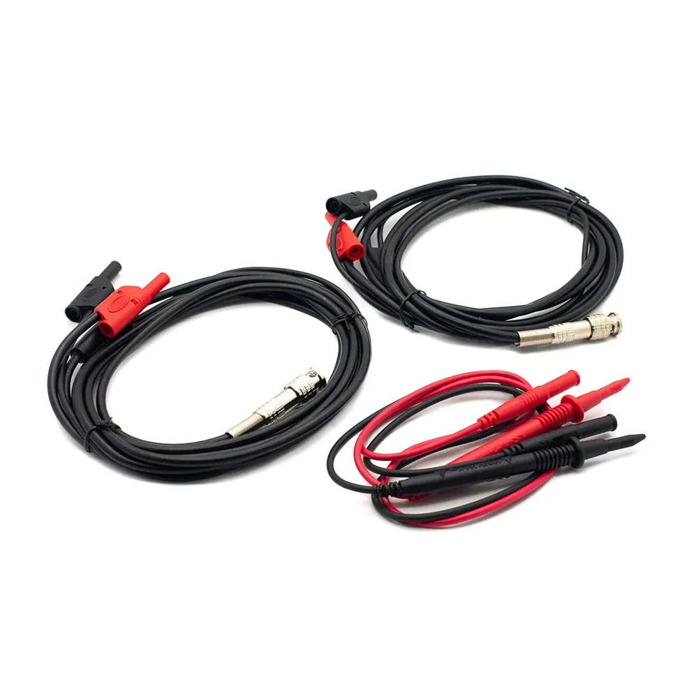
Item Picture:


There are no reviews yet.